Building a simple Bootloader in Assembly
Published: September 25, 2025 | Tags: #assembly #low level
Building a bootloader is just another necessary chapter if you truly want to dive into low-level computer systems or OS development. In this article we will explore how is the process of creating a simple 16-bit bootloader in assembly, explaining how to print text directly from the initial startup phase.

But, first. What happens when you press Power?
Before any operating system, kernel or basic graphic interface can even load, we find a piece of firmware that takes control. We are talking about the BIOS (the Basic Input/Output System).
Let’s explore what it does:
- First the BIOS does some checks on the hardware.
- Then it looks for a bootable device (such as hard drive, SSD, USB or floppy disk). It checks devices in a pre-configured order which you can modify.
- When a bootable device is found, the BIOS reads its first sector (512 bytes) into a specific memory address (
0x7C00). - For a sector to be considered bootable it must end with the following magic number:
0xAA55. If it’s present, the BIOS will consider it a valid bootloader. - Now, after everything, the BIOS performs a
JMPinstruction to0x7C00, transfering control to the code of your bootloader.
Actually pretty simple! At this point the CPU is in 16-bit Real Mode, which is a state compatible with the original IBM PC. This mode has direct memory access and a segmented memory model.
It’s simpler but more restrictive than the 32-bit/64-bit protected modes we use with our modern OS.
History time!
At least in my case, before diving into actual code I enjoy understanding the theory and context behind. We have already talked about how it works fundamentally, but there will still be numbers and decisions that you could consider illogical without some history!
Well, many of the standards we are about to use are historical artifacts that trace back to the birth of the personal computer.
THE IBM PC and the BIOS (1981).
So, the whole saga starts with the original IBM PC. Its designers needed a simple and extensible way to start the machine and load the OS from a floppy disk.
To solve this, they created the BIOS, which is stored on a ROM chip on the motherboard.
The CPU in the IBM PC was the Intel 8088, which operated in the 16-bit mode (now known as Real Mode). This mode could only address 1 megabyte of RAM, which was A LOT back then.
About 0x7C00.
The IBM PC had 64KB of RAM (in its base model). The engineers had to decide where in this memory to load the 512-byte boot sector from the floppy disk.
This might seem simple, but they needed a location that wouldn’t interfere with other critical system info, like the Interrupt Vector Table (IVT, located at the beginning of memory), the BIOS Data Area (BDA, located just after the IVT), and the operating system itself (which needed as much free contiguous memory as possible).
Therefore, considering these constrains, they chose 0x7C00.
It was a “safe” address, high enough in the first 32 KB of RAM leaving room below it for the OS (like PC-DOS) to set up its own data structures. This address chosen quite a while ago has been preserved for backward compatibility. Every x86-compatible computer today still loads the boot sector to this address when booting in legacy BIOS mode.
About 0xAA55.
I mean, how could the BIOS know if a disk was actually bootable? It couldn’t analyze the code in the first sector.
Solution? Some trust and the magic number 0xAA55. This 2-byte value had to be located at the end of the 512-byte sector.
The values AA and 55 in binary are 10101010 and 01010101. This pattern was unlikely to occur by chance in random data or text, therefore it was reliable enough.
If the BIOS finds this signature, it considers the disk as bootable and jumps to 0x7C00, if not it moves on.
You might be asking yourself… What if the random data actually ends with 0xAA55 in the first sector. While theoretically possible, it is really unlikely, and even if it happened, it would cause the drive to return a hardware-level read error to the BIOS long before the BIOS could even check the signature. Still, if you feel like it could happen, UEFI, which is the modern way, does not rely on simple magic numbers.
Setting up the Development Environment (Debian/Ubuntu).
To build our bootloader we will need a few tools. First one is NASM (Netwide Assembler) to conver our assembly code into a flat binary. We also need QEMU (Quick EMUlator), to run our bootloader without affecting the actual hardware.
We can install these on a Debian-baed system with:
sudo apt-get update
sudo apt-get install -y nasm qemu-system-x86
Direct Video Memory Access.
Our bootloader will print text to the screen. In our case, the easiest way to do this is by writing directly to the video memory.
Things to know:
- The text-mode video memory starts at address
0xB8000(also derives from IBM PC, we should talk about IBM PC in an article). - Each character on the screen occupies two bytes. Might seem weird at first, but the first one is the ASCII value while the second is the “color attribute” byte (doing
0x0Fgets you white on black,0x0Agreen on black).
A screen resolution of 80 columns by 25 rows means there are 2000 character positions!
Time to code!
While it is assembly, I tried to make sure the code is documented enough. If you do not know asembly, you should still understand the logic behind it.
[org 0x7c00] ; Tell NASM our code will be loaded at 0x7C00.
start:
; Initialize segment registers. In 16-bit real mode, these are crucial
; for addressing memory. Setting them to 0 gives us a flat, 64KB segment
; starting at physical address 0, which is useful for simple operations.
mov ax, 0
mov ds, ax ; DS (Data Segment) register
mov es, ax ; ES (Extra Segment) register
; **Take control of the screen**
call clear_screen
; **Print our first message**
; We'll use our 'print_string' function. It expects parameters in registers.
mov si, msg1 ; SI holds the address of the first string.
mov dh, 5 ; DH holds the row (Y-coordinate).
mov dl, 10 ; DL holds the column (X-coordinate).
mov bh, 0x0F ; BH holds the color attribute (white on black).
call print_string ; Call our reusable function.
;**Print another message**
mov si, msg2 ; SI holds the address of the second string.
mov dh, 7
mov dl, 20
mov bh, 0x0A ; (bright green on black).
call print_string
hang:
cli ; Clear interrupts: isable all hardware interrupts.
hlt ; Halt: stop the CPU. This prevents the CPU from
; executing garbage instructions after our code finishes.
; **Function to clear the screen**
; This function clears the screen by filling video memory with spaces.
clear_screen:
; Video memory starts at 0xB8000 as we said. Set ES to this segment.
mov ax, 0xb800
mov es, ax
mov di, 0 ; DI (Destination Index) points to the start of video memory offset.
mov cx, 2000 ; CX (Count register) for 80 columns * 25 rows = 2000 characters.
mov ax, 0x0720 ; AX = Character (0x20 for space) + Attribute (0x07 for light grey on black).
; This means we're writing a light grey space on a black background.
rep stosw ; Repeat STORe Word: store AX at [ES:DI], then DI += 2, CX--.
; This clears the entire screen very quickly.
ret ; Return from the function.
; **Function to print a string to a screen location**
; Parameters (we pass them as registers):
; SI: Address of the null-terminated string to print.
; DH: Row number (0-24).
; DL: Column number (0-79).
; BH: Color attribute (0x0F for white, 0x0A for green).
print_string:
; Setup ES:DI to point to the correct video memory location for our character.
; Video memory segment.
mov ax, 0xb800
mov es, ax
; Calculate the DI offset: (row * 80 + col) * 2 bytes/char
; Some maths, I know.
mov al, 80 ; AL = 80 (columns per row).
mul dh ; AX = DH (row) * 80.
add al, dl ; AL = (AX_low + DL_low) = (row * 80) + column.
adc ah, 0 ; Add carry from AL to AH (handles overflow for 16-bit AX).
; This completes AX = (row * 80 + col).
shl ax, 1 ; Multiply AX by 2 (since each character takes 2 bytes).
mov di, ax ; DI now holds the final offset into video memory.
print_loop:
lodsb ; LOaD String Byte: loads byte from [DS:SI] into AL, then SI increments.
cmp al, 0 ; Compare AL with 0 (null terminator).
je .done ; If AL is 0, jump to .done (end of string).
mov ah, bh ; Move the color attribute (from BH) into AH.
; Now AX contains (Attribute | Character).
mov [es:di], ax ; Move the combined AX (char + attr) into video memory at ES:DI.
add di, 2 ; Increment DI by 2 to point to the next character's cell.
jmp print_loop ; Loop back to print the next character.
.done:
ret ; Return from the print_string function.
; **Data section**
; Our null-terminated strings. 'db' means "define byte".
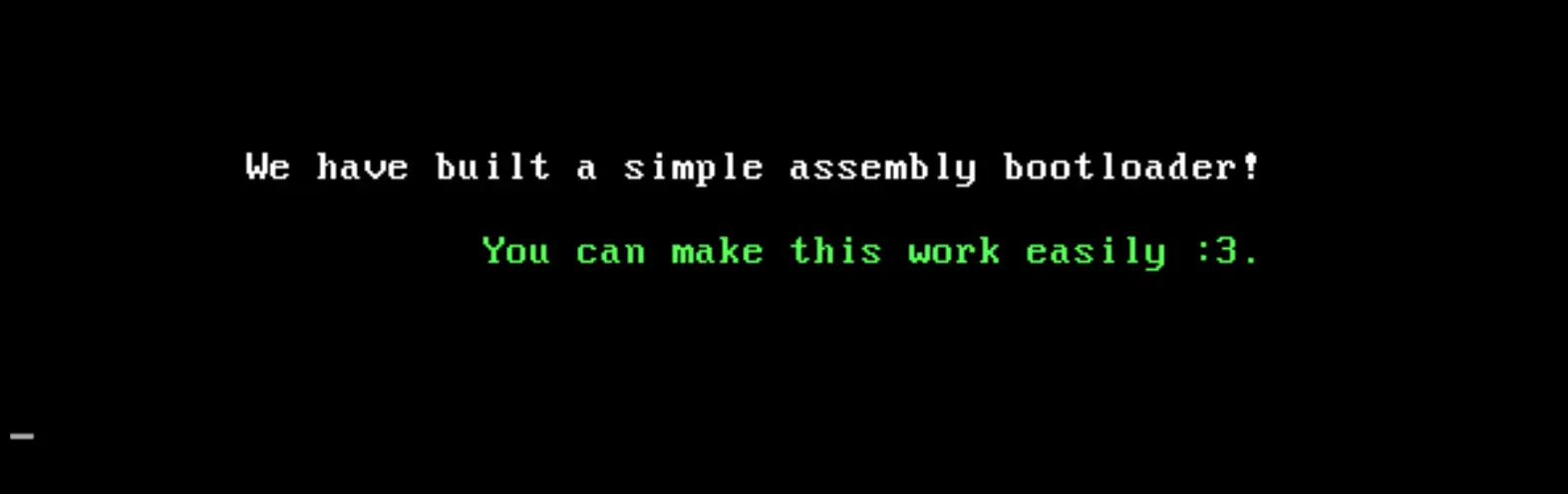
msg1 db 'We have built a simple assembly bootloader!', 0
msg2 db 'You can make this work easily :3.', 0
; **Bootloader signature**
; This padding ensures our bootloader is exactly 512 bytes long.
times 510-($-$$) db 0 ; Fill remaining bytes up to 510 with zeros.
dw 0xaa55 ; Define Word: Place the magic number at byte 510-511.
Compiling and running.
As you can see, it’s not that complex. With our file saved, we use NASM to assemble it and run it in our emulator!
nasm -f bin boot.asm -o boot.bin
qemu-system-i386 -fda boot.bin
QEMU will emulate a machine booting from a floppy disk (represented by boot.bin, and you will see your messages printed clear on the screen.
Conclusion.
In just an article you have been able to build a fundamental piece in your computer! But, this is not the end. This is the beginning. From this you could implement more functions, load more code, or even switch to Protected Mode, which is necessary to run C/C++ kernels and access more than 1MB of RAM.
If you find this interesting, it’s time to experiment more!